

Grating load tables
GRP grating load calculator, span guide and selection route.
Start with clear span, applied load, surface type and support direction before choosing standard mesh, mini mesh, solid top or pultruded slab-style GRP flooring.
Preliminary grating calculator
This tool gives a conservative route-finding result for early selection. Default values are visible even if scripting is blocked; when scripting runs, the result updates from the inputs.
Preliminary result
Final selection must be checked against supplier datasheets, actual support centres, fixings, deflection limits, resin/fire requirement and project standards.
The four inputs that control the answer
The strongest technical pages in this market do not just show a table; they teach the customer which numbers matter. These are the checks we need before recommending a product route.
Clear span
Measure the unsupported distance between bearing supports. Do not confuse panel size with span.
Load type
Uniform pedestrian load, point loads, trolleys and plant maintenance loads need different caution levels.
Surface type
Standard mesh drains; mini mesh reduces openings; solid top closes the surface; slab routes are more directional.
Support detail
Bearing width, fixing clips, cut-outs, removable covers and edge conditions can change the route.
Indicative route table
Use this as a structured enquiry guide. It is intentionally conservative and should be replaced by product-specific datasheet values when finalising a project.
| Product route | Best fit | Typical checks | Ask us for |
|---|---|---|---|
| Standard mesh | General walkways, platforms, gantries, wet access and drainage-friendly areas. | 25/38/50 mm depth, span, UDL, point load, clips and cut-outs. | Standard mesh guidance |
| Mini mesh | Smaller openings, small wheels, public-facing maintenance routes and dropped-object reduction. | Opening size, cleaning, footwear, span, duty and edge support. | Mini mesh guidance |
| Solid top | Closed anti-slip surfaces, service covers, debris/spill control and visual screening. | Drainage, panel weight, support centres, fixing access and cut edge treatment. | Solid top guidance |
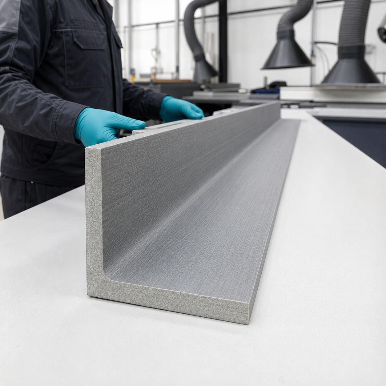
| Pultruded slab | Directional strength, engineered spans and support-led access floors. | Span direction, deflection, bearing, load path, environment and drawings. | Pultruded slab route |
When to stop and ask for technical support
A calculator is useful for early routing, but some situations need review before purchase.
Send the span before guessing the thickness.
Give us the product route, clear span, applied load, environment and any cut-outs. We can help move the enquiry into a stocked panel, cut-to-size order or project support route.
Technical grating checkpoint
Read a grating load table as a serviceability tool
The meaningful result is not simply the load a panel survives. Selection normally depends on acceptable movement under the design point load or distributed load at the actual clear span.
| Specification area | What to establish | Engineering boundary |
|---|---|---|
| Point load | Magnitude, contact area, position and deflection at span. | A small concentrated load can govern even where UDL capacity appears high. |
| UDL | Total distributed pressure and supported area. | Do not compare kN with kN/m² or omit the loaded width. |
| Serviceability vs ultimate | Allowable deflection and safety factors versus failure/ultimate capacity. | Passing an ultimate test does not prove acceptable walking comfort or project deflection. |
| Supports and fixings | Bearing width, continuity, clips, uplift and panel joints. | The calculator assumes the stated support condition; site framing must reproduce it. |
Important: Calculator outputs are preliminary selection information unless the project explicitly accepts them. The responsible designer must verify loads, combinations, supports and governing criteria.
Useful routes: GRP grating buying guide, cut-to-size quote and project technical support.
Calculator interpretation guide
A PASS result is a preliminary data check—not approval of the installed floor
The calculator compares stated inputs with its underlying grating data. It cannot confirm that the entered load, unsupported span, product identity, support condition or safety factor is correct for the project.
Validate the inputs
- Measure clear unsupported span between bearing faces.
- Enter the governing service load in consistent units.
- Confirm the raw table belongs to the exact product and span direction.
- Use the project’s required safety and serviceability basis.
Understand the output
- Interpolated values are estimates between tabulated data points.
- Design allowable UDL and utilisation reflect the entered assumptions.
- PASS/FAIL does not check point loads, wheels, cut-outs or damaged panels.
- Review deflection as well as capacity.
Check the installed system
- Verify support width, condition and reactions.
- Confirm orientation, joints, cut edges and penetrations.
- Specify compatible hold-down and panel-joining fixings.
- Check slip, opening, fire, resin and environmental requirements separately.
Do not convert between load cases casually
A UDL, a concentrated pedestrian load and a wheel load act differently. The loaded area, position, panel width, dynamic effects and local response matter. Use the correct product evidence for each governing case rather than converting solely by total force.
Technical review triggers
- Input outside the raw data range or reliance on extrapolation.
- Non-standard panel width, narrow strips, penetrations or cantilevers.
- Wheeled, impact, sustained, fatigue or vehicle loading.
- Public access, machinery access or unusual consequence of failure.
- Unverified product identity, resin, support or deterioration.
Load-calculator FAQs
What does unsupported span mean?
It is the clear distance the grating bridges between the relevant bearing faces, measured in the verified load-bearing direction—not the overall panel length.
Is an interpolated result the same as a tested value?
No. It is an estimate between raw data points. Confirm that interpolation is appropriate and do not extrapolate beyond the verified data range without technical evidence.
Does PASS include concentrated loads and deflection?
Only if those checks are explicitly represented by the calculator and its data. Otherwise they remain separate design checks for the exact product and installation.
Can the result be used as a structural calculation?
No. Retain it as a preliminary selection record and obtain project-specific verification where design responsibility, non-standard geometry or unverified loading is involved.
Continue the load route
Move from load checks into grating selection, optimisation and support.
These routes help customers use span guidance in context rather than treating load tables as a dead-end technical page.